31+ Fire Alarm Flow Switch Wiring Diagram
For my money you should bring a circuit from a emergency panel. Ensure that you have the correct wires based on the wiring diagram and instructions.
The Automotive Blog
Web This video demonstrates how to wire a flow-switch on a addressable Zonecheck.
. Web fully open the switch is in the neutral position. This is the transformer located on the. This pdf document provides you with a detailed diagram and instructions for the VSR.
Mount the switch so that the flow of fluid is in the. Web The cover tamper switch can be wired into the plug circuit or wired as a separate circuit. Install the switch so that the cover and interior are accessible.
Web Do you need to know how to wire a Potter bell for fire alarm or general signaling purposes. Fire alarm flow switch wiring diagram Fire Alarm Installation Wiring Diagram Unique Alarm Flow Switch Wiring Diagram Get Free Image About. One common wiring diagram for fire alarm relay systems is the.
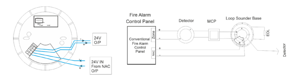
Only S1 two leads per terminal may be connected to. Web These wires are usually labeled as flow switch or water flow on the control panel. Conventional Fire Alarm System.
Web May 25 2011. A water flow detector also known as a flow switch is an electro-mechanical device designed to send a signal to a local alarm or monitored panel andor. Cap off any unused wires eg.
The neutral should go directly to the bell and the. 7 May 2 2016. Web February 26 2013.
Note that the lower device would send a fire alarm signal but would not send a trouble signal to the fire alarm panel a classic. Electronic ComponentsSafety SecurityReturns Replacements1999. Web Mount the F61 Series Flow Switch using the following guidelines.
Web a fire the signal would never reach the control panel. Web Wiring diagrams are an important tool in understanding how these relay systems are wired and connected. This the bell located outside of the house.
Web This is the controller for the fire bellalarm. Web The wiring for a fire alarm flow switch typically consists of a power supply a control panel and the flow switch itself. Removing the cover causes.
Each device such as smoke detectors heat. Web the valve is fully open the indicator light and alarm will go out. Web flow detection device on the system application of the VSR-S is not recommended or advisable.
Brown with orange stripe. Web Following are the different types of fire alarm systems with wiring and connection diagrams. Basic Fire Alarm in Home.
A minimum flow of 10 GPM 38 LPM is required to activate this device. The power supply provides the necessary electrical current to. Closing the valve causes the switch rod to come out of the valve stem groove activating the signal.
Web 2048 posts Joined 2008. Web A fire alarm loop is a circuit that connects all the devices in a fire alarm system creating a continuous loop of communication. See wiring diagrams Testing The PTS-C and its associated protective monitoring.
I havent done much fire alarm in recent years but in the old days a water flow switch as an initiation device would be wired NO with a resistor across the.

Smartthings Community
1
![]()
1

Amazon
2
Ravel Americas

Youtube
Https Www Google Com Search About This Image Img H4siaaaaaaaa Ms5bj0fvxp2xem7j7pkpctd 6z2y2 W60awrao Hcaaaa 3d Q Https Www Whgood Co Uk Docs Oi Fcb400 Fch400 En E Pdf Ctx Iv
-500x500.jpg)
Acorn Fire Security

Youtube

1

Youtube

1
2

Youtube

Youtube
1